Forums
Good day
I am attempting to simulate the response of a wideband cable that is faulted at the receiving end. However, whenever I inject a step pulse into the cable, I do not see any current reflections at the fault switch. I have double-checked the continuity, fault switching times, and signal properties.
The injected pulse is a 50V step wave with a 10ms on time. The fault is an SLG at 0s until infinity. The fault occurs on the C phase while a and b on the cable are grounded so are the sheaths.
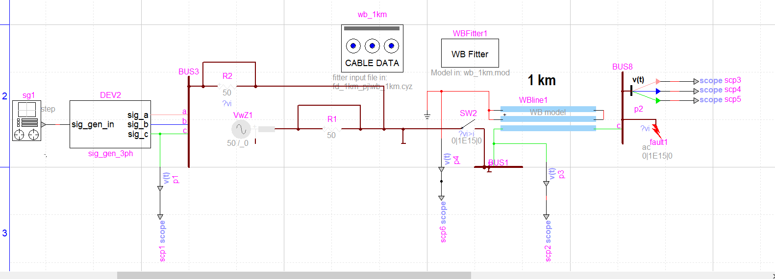
The circuit and cable parameters are shown below I have already applied DC Correction in the fitter.
![]()
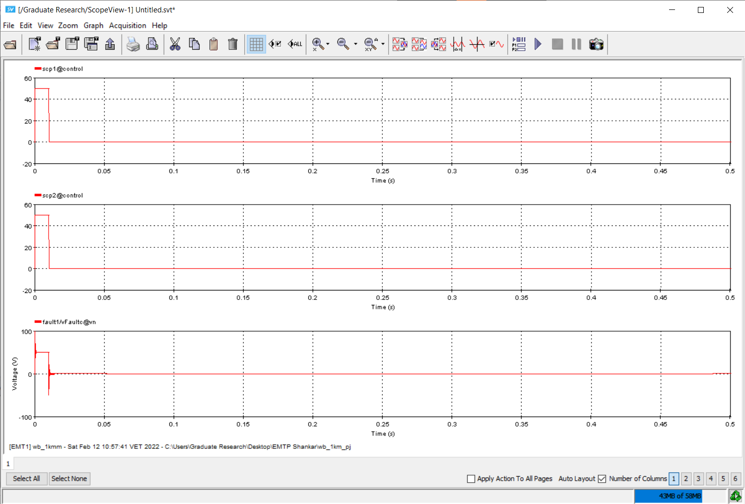
The circuit and traces are shown below
Cable Data
Please see the spreadsheet below for the cable data. I attempted to format it in HTML as well as pasting as an image but to no avail
https://myuwi-my.sharepoint.com/:x:/g/personal/shankar_ramharack_my_uwi_edu/EYjK1A_KarVMskeyAtLHufoBXcrM5kqPth3rk9SMVrUISQ?e=xccCLO
Hi Shankar, Maybe you…
Hi Shankar,
Maybe you should zoom on your current waveform. If you cable is 1km, the travelling wave reflection delay would be between 1-10us I believe.
In reply to Hi Shankar, Maybe you… by h.gras
Zooming
Hi gras,
So are you saying that the ends of the waveform where ringing is seen are actually the fault reflections? I was told that this was just switching transients. When I zoom in I see an envelope that goes to the steady-state flat line. as seen above.